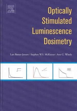
Optically Stimulated Luminescence Dosimetry
Autor L. Boetter-Jensen, S.W.S. McKeever, A.G. Wintleen Limba Engleză Hardback – 23 oct 2003
The book will find use in those laboratories within academia, national institutes and the private sector where research and applications in radiation dosimetry using luminescence are being conducted. Potential readers include personnel involved in radiation protection practice and research, hospitals, nuclear power stations, radiation clean-up and remediation, food irradiation and materials processing, security monitoring, geological and archaeological dating, luminescence studies of minerals, etc.
Preț: 1291.45 lei
Preț vechi: 1769.10 lei
-27% Nou
Puncte Express: 1937
Preț estimativ în valută:
247.11€ • 258.70$ • 204.47£
247.11€ • 258.70$ • 204.47£
Carte tipărită la comandă
Livrare economică 05-19 aprilie
Preluare comenzi: 021 569.72.76
Specificații
ISBN-13: 9780444506849
ISBN-10: 0444506845
Pagini: 374
Dimensiuni: 156 x 234 x 22 mm
Greutate: 0.7 kg
Editura: ELSEVIER SCIENCE
ISBN-10: 0444506845
Pagini: 374
Dimensiuni: 156 x 234 x 22 mm
Greutate: 0.7 kg
Editura: ELSEVIER SCIENCE
Cuprins
PREFACE.CHAPTER 1: INTRODUCTION.
1.1Optically stimulated luminescence.1.2Historical development of OSL dosimetry.1.3 OSL dosimetry.1.3.1Personal dosimetry.1.3.2Environmental dosimetry.1.3.3Medical dosimetry.1.3.4Retrospective dosimetry.1.4 This book.
CHAPTER 2: OPTICALLY STIMULATED LUMINESCENCE THEORY.
2.1 Stimulated luminescence.2.2 Generalised mathematical description of opticallystimulated luminescence.2.3The photoionisation cross-section.2.3.1 Optical transitions.2.3.2 Wavelength dependence.2.3.3 Measurement of the photoionisation cross-section.2.4CW-OSL.2.4.1 Models and rate equations.2.4.2 The one-trap/one-centre model.2.4.3 Models containing multiple-traps and centres.2.4.4 A more generalised model.2.4.5 Temperature dependence effects.2.4.6 Thermal quenching.2.5LM-OSL.2.5.1 First-order and general-order-kinetics.2.5.2 Relationship between LM-OSL and CW-OSL.2.5.3 Wavelength dependence of LM-OSL.2.5.4 Photoconductivity.2.6Pulsed OSL.2.6.1 Principles of POSL.2.6.2 Delayed OSL (DOSL).2.7Phototransferred effects.2.7.1Procedure.2.7.2Mathematical description and typical data.2.8Radiophotoluminescence.2.8.1 Procedure.
CHAPTER 3: OSL PROPERTIES OF SYNTHETIC MATERIALS.
3.1 Al2O3. 3.1.1 Introduction.3.1.2 Crystal growth.3.1.3 OSL stimulation and emission characteristics ofAl2O3:C. 3.1.4 The OSL response of Al2O3:C to radiation exposure.3.1.5 The temperature dependence of OSL from Al2O3:C. 3.1.6 Zeroing of the OSL signal fromAl2O3:C. 3.2 Halides.3.2.1 KCl.3.2.2 KBr.3.2.3 NaCl.3.2.4 RbI.3.2.5 CaF2.3.2.6 BaFX (X≡Br, Cl, I).3.3 Sulphates.3.3.1 MgSO4.3.3.2 CaSO4.3.4 Sulphides.3.4.1 AS (A ≡ Mg, Sr, Ca, Ba).3.5 Oxides.3.5.1 BeO.3.5.2 Fused quartz.
CHAPTER 4: PASSIVE OPTICALLY STIMULATED LUMINESCENCEDOSIMETRY.
4.1. Personal dosimetry.4.1.1 Introduction.4.1.2 Landauer's LuxelTM personal dosimetrysystem.4.1.3 Landauer's InLightTM personaldosimetry system.4.1.4 Beta dosimetry.4.1.5 POSL imaging.4.2. Environmental OSL dosimetry usingAl2O3.4.2.1 Measurement of the natural terrestrial background radiation.4.2.2 Measurement of the natural space backgroundradiation.4.3. UV dosimetry. 4.4. OSL and RL remote optical fibre dosimetry in medicalapplications.4.4.1 Real-time in-vivo monitoring of doses duringradiotherapy.4.4.2 Optical fibre dosimeters.
CHAPTER 5: OSL PROPERTIES OF NATURAL MATERIALS.
5.1 Quartz.5.1.1Crystal structure and point defects.5.1.2Decay curve shapes obtained under continuousstimulation - CW-OSL.5.1.2.1 Stimulation sources.5.1.2.2 Effect of the 110 °C trap.5.1.2.3 Dependence on power.5.1.2.4 Three components.5.1.2.5 Effect of stimulation wavelength.5.1.2.6 Effect of stimulation temperature.5.1.3Linear modulation OSL - LM-OSL.5.1.3.1 LM-OSL at 160 °C with 470 nmstimulation.5.1.3.2 LM-OSL at different temperatures with 526nm stimulation.5.1.4 Pulsed OSL.5.1.4.1.1 TRL.5.1.4.1.2 DOSL or OSA.5.1.5Excitation spectra.5.1.5.1 Bleaching response spectrum.5.1.5.2 Excitation spectra after bleaching by 514± 25 nm light.5.1.5.3 Continuous scanning of stimulationwavelengths.5.1.5.4 Excitation interference filters and usingxenon lamp.5.1.5.5 Excitation using laser lines from 458 to645 nm.5.1.5.6 Stimulation in the infrared 780 - 920nm.5.1.6Emission spectra.5.1.6.1 OSL emission spectra.5.1.6.2 TL emission spectra.(i)360 - 420 nm (near UV to violet). (ii)420 - 490 nm (blue). (iii) 590 - 650 nm (orange).5.6.1.3 Radioluminescence.5.1.7Dose dependence.5.1.7.1 Fast component.(i) Multiple aliquot data.(ii) Single aliquot data.(iii) Single grain data.5.1.7.2 Low doses.5.1.8Effects of previous thermal treatment.5.1.8.1 High temperature annealing - above 500°C.(i) Comparison of LM-OSL, TL, RL andEPR.(ii) CW-OSL growth curves afterannealing.5.1.8.2 Low temperature annealing - 160 to 280°C.5.1.8.3 Thermal stability.(i) Isothermal decay.(ii) Pulse annealing.5.1.8.4 Irradiation at elevated temperature.5.1.8.5 Thermal transfer.5.1.9Raised temperature OSL.5.1.9.1 Thermal quenching.5.1.9.2 Thermal assistance.5.1.10The slow component.5.1.10.1 Thermal stability.5.1.10.2 Growth curve.5.1.10.3 Optical bleaching.5.1.11Photoionisation cross-section.5.1.12 Modelling processes that give rise to OSL in quartz.5.1.3Summary.
5.2 Feldspars.5.2.1 Crystal structure.5.2.2Decay curve shape obtained under continuousstimulation - CW-OSL and CW-IRSL.5.2.2.1 Stimulation sources.5.2.2.2 Effect of stimulation temperature.(i) initial signal.(ii) decay curve shape.5.2.3Linear modulation IRSL (LM-OSL).5.2.4 Pulsed OSL and IRSL.5.2.4.1 Pulsed OSL.5.2.4.2 Pulsed IRSL.5.2.4.3 Optically stimulated afterglow.5.2.5 Excitation spectra.5.2.5.1 Direct measurements.5.2.5.2 Bleaching response spectrum.5.26 Emission spectra.5.2.6.1 IRSL emission spectra.(i) 280-290 nm (nearUV).(ii) 320-340 nm (nearUV).(iii) 390-440 nm (violet/blue).(iv) 550-570 nm (yellow/green).(v) 600-750 nm (red/far red).5.2.6.2 TL emission spectra.5.2.6.3 RL emission spectra.(i) under X-ray stimulation at lowtemperature.(ii) under X-ray stimulation above roomtemperature.(iii) under beta stimulation from a137Cs source.5.2.6.4 PL emission spectra.5.2.7 Effects of previous optical treatment.5.2.7.1 Bleaching at ambient temperature.5.2.7.2 IR bleaching at elevated temperature.5.2.8 Effects of previous thermal treatment.5.2.8.1 Preheating of laboratory and naturallyirradiated samples.5.2.8.2 Pulse annealing.5.2.8.3 Irradiation at elevated temperature.5.2.9 Raised temperature IRSL and OSL.5.2.9.1 Thermal quenching.5.2.9.2 Thermal assistance.(i) above room temperature.(ii) below room temperature.(iii) wavelength dependence.(iv) link to anomalous fading.5.2.10 Anomalous fading.5.2.10.1 TL, OSL and IRSL.5.2.10.2 Attempts to remove anomalous fading.(i) using a preheat.(ii) using an optical treatment.5.2.10.3 Attempts to avoid anomalous fading.(i)using timeresolved measurements.(ii)using different detection wavelengths.5.2.10.4 CL and TL spectra of fadingfeldspars.5.2.10.5 Low temperature phosphorescence.5.2.10.6 Single grain IRSL fading and fadia plots.5.2.10.7 Logarithmic signal decay.5.2.10.8 Correcting for anomalous fading.5.2.11 Radioluminescence.5.2.11.1 A new dating method.5.2.11.2 Practical considerations.5.2.11.3 Methods of De determination.5.2.11.4 Thermal stability.5.2.11.5 Single grain measurements.5.2.12 Models for IRSL, OSL, IR-RL in feldspars.5.2.12.1 IRSL.5.2.12.2 OSL.5.2.12.3 IR-RL.5.2.12.4 Comparison of IR-RL and IRSL (orOSL).
5.3 Conclusions.
CHAPTER 6: RETROSPECTIVE OSL DOSIMETRY.
Part I: RETROSPECTIVE ACCIDENT DOSIMETRY.6.1. Introduction.6.2. Materials and sampling.6.3. Sample preparation and experimental details.6.4. Determination of the accident dose.6.4.1 Retrospective assessment of environmental doserates.6.4.2 Estimation of the accident dose.6.5. Analytical protocols.6.5.1 Introduction.6.5.2 Multiple-aliquot protocols.6.5.3 The Single Aliquot Regeneration and Added Dose(SARA)protocol.6.5.4 True single-aliquot protocols.6.5.4.1 Introduction.6.5.4.2 Variation of OSL signal with preheat.6.5.4.3 Choice of OSL signal.6.5.4.4 Sensitivity changes with regeneration cycles.6.5.4.5 The single-aliquot regeneration (SAR)protocol.6.6. Evaluation of dose-depth profiles in bricks.6.6.1 Continuous OSL scanning. 6.6.2 Determination of depth-dose profiles fromChernobyl bricks.6.6.3 Absolute errors and estimated precision of theequivalent dose in bricks.6.7. Retrospective OSL dosimetry using unheated quartz. 6.7.1 Dose distributions.6.7.2 Thermal transfer and sensitivity changes.6.7.3 Concrete.6.8 Retrospective OSL dosimetry using household and workplacechemicals.6.9 Retrospective OSL dosimetry using porcelain.6.9.1 Introduction.6.9.2 The origin of OSL in porcelain.6.9.2.1 Time-decaying dose-dependent OSLsignals.6.9.2.2 Time-steady PL emission spectra fromporcelain.6.9.2.3 OSL stimulation spectra.6.9.3 OSL dose response of porcelain.6.9.4 Dose-depth profiles in porcelain and the effectof transparency.6.9.5 OSL dosimetry using porcelain dental crowns.6.10Retrospective accident dosimetry - conclusions.
Part II: GEOLOGICAL AND ARCHAEOLOGICAL DATING.
6.11 Measurement Procedures.6.11.1 Multiple-aliquot methods.6.11.2 Single-aliquot methods.6.11.2.1 Feldspars.(i) Additive dose.(ii) Regenerative dose.6.11.2.2 Quartz.(i) Additive dose.(ii) Regenerative dose.6.11.2.3 Luminescence sensitivity.(i) Multiple luminescence signals.(ii)Comparison of the 110 °C TL peak andOSL.6.11.2.4 Reliability of OSL monitoring of sensitivity change.6.11.3 Dose distributions for single aliquots.6.11.3.1 Histograms.6.11.3.2 Probability plots.6.11.3.3 Radial plots.6.11.3.4 Calculation of De.6.12 Single grains.6.12.1 Measurements.6.12.1.1. Feldspars.6.12.1.2 Quartz.6.12.2 Dose distributions for single grains.6.12.2.1 Histograms.6.12.2.2 Probability plots.6.12.2.3 Radial plots.6.12.2.4 Calculation of De.6.13 Geological and archaeological dating-conclusions.
CHAPTER 7: OSL MEASUREMENT TECHNOLOGY.
7.1 Stimulation modes.7.1.1 CW-OSL. 7.1.2 LM-OSL.7.1.3 POSL.7.2 The light detection system.7.2.1Photomultiplier tubes.7.2.2 Imaging photon detectors.7.2.3 Solid state detectors.7.3Automated OSL readers.7.4 Development of optical stimulation sources.7.4.1 Laser stimulation.7.4.2 IR LED stimulation.7.4.3 IR laser diode stimulation.7.4.4 Broad-band light stimulation. 7.4.5Optimisation of OSL detection.7.4.6Green LED stimulation.7.4.7Blue LED stimulation.7.4.8Blue LED and cut-off filter characteristics. 7.4.9Ramping the LEDs.7.4.10 Pulsed and time-resolved OSL.7.5 Wavelength resolved OSL.7.5.1Stimulation spectrometry.7.5.2 Emission spectrometry.7.6Imaging systems.7.7 Single grain OSL systems.7.7.1 Introduction.7.7.2 CCD luminescence imaging systems.7.7.3 Single grain laser OSL systems.7.8 Automatic OSL scanners.7.9Portable systems for OSL measurements in the field.7.10 The measurement of radioluminescence.7.11 Commercially available OSL apparatus.7.12 Future developments.
