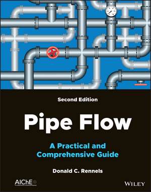
Pipe Flow: A Practical and Comprehensive Guide, 2nd Edition
Autor D Rennelsen Limba Engleză Hardback – 26 mai 2022
Preț: 751.46 lei
Preț vechi: 988.77 lei
-24% Nou
Puncte Express: 1127
Preț estimativ în valută:
143.84€ • 156.29$ • 120.90£
143.84€ • 156.29$ • 120.90£
Carte disponibilă
Livrare economică 31 martie-14 aprilie
Livrare express 14-20 martie pentru 52.75 lei
Preluare comenzi: 021 569.72.76
Specificații
ISBN-13: 9781119756439
ISBN-10: 111975643X
Pagini: 384
Dimensiuni: 218 x 291 x 26 mm
Greutate: 1.16 kg
Ediția:2nd Edition
Editura: Wiley
Locul publicării:Hoboken, United States
ISBN-10: 111975643X
Pagini: 384
Dimensiuni: 218 x 291 x 26 mm
Greutate: 1.16 kg
Ediția:2nd Edition
Editura: Wiley
Locul publicării:Hoboken, United States
Cuprins
Preface to the First Edition xix
Preface to the Second Edition xxi
Nomenclature xxiii
Part I Methodology 1
1 Fundamentals 3
1.1 System of Units 3
1.2 Fluid Properties 4
1.2.1 Pressure 4
1.2.2 Temperature 5
1.2.3 Density 6
1.2.4 Viscosity 6
1.2.5 Energy 7
1.2.6 Heat 7
1.3 Velocity 8
1.4 Important Dimensionless Ratios 8
1.4.1 Reynolds Number 8
1.4.2 Relative Roughness 9
1.4.3 Loss Coefficient 9
1.4.4 Mach Number 9
1.4.5 Froude Number 9
1.4.6 Reduced Pressure 10
1.4.7 Reduced Temperature 10
1.4.8 Ratio of Specific Heats 10
1.5 Equations of State 10
1.5.1 Equation of State of Liquids 10
1.5.2 Equation of State of Gases 11
1.5.3 Two-Phase Mixtures 11
1.6 Flow Regimes 12
1.7 Similarity 12
1.7.1 The Principle of Similarity 12
1.7.2 Limitations 13
References 13
Further Reading 13
2 Conservation Equations 15
2.1 Conservation of Mass 15
2.2 Conservation of Momentum 15
2.3 The Momentum Flux Correction Factor 17
2.4 Conservation of Energy 18
2.4.1 Potential Energy 18
2.4.2 Pressure Energy 19
2.4.3 Kinetic Energy 19
2.4.4 Heat Energy 19
2.4.5 Mechanical Work Energy 20
2.5 General Energy Equation 20
2.6 Head Loss 21
2.7 The Kinetic Energy Correction Factor 21
2.8 Conventional Head Loss 22
2.9 Grade Lines 23
References 23
Further Reading 23
3 Incompressible Flow 25
3.1 Conventional Head Loss 25
3.2 Sources of Head Loss 26
3.2.1 Surface Friction Loss 26
3.2.1.1 Laminar Flow 26
3.2.1.2 Turbulent Flow 26
3.2.1.3 Reynolds Number 27
3.2.1.4 Friction Factor 27
3.2.2 Induced Turbulence 29
3.2.3 Summing Loss Coefficients 31
References 31
Further Reading 32
4 Compressible Flow 33
4.1 Introduction 33
4.2 Problem Solution Methods 34
4.3 Approximate Compressible Flow using Incompressible Flow Equations 34
4.3.1 Using Inlet or Outlet Properties 35
4.3.2 Using Average of Inlet and Outlet Properties 35
4.3.2.1 Simple Average Properties 35
4.3.2.2 Comprehensive Average Properties 36
4.3.3 Using Expansion Factors 37
4.4 Adiabatic Compressible Flow with Friction: Ideal Equations 39
4.4.1 Shapiro's Adiabatic Flow Equation 39
4.4.1.1 Solution when Static Pressure and Static Temperature Are Known 39
4.4.1.2 Solution when Static Pressure and Total Temperature Are Known 41
4.4.1.3 Solution when Total Pressure and Total Temperature Are Known 41
4.4.1.4 Solution when Total Pressure and Static Temperature Are Known 42
4.4.2 Turton's Adiabatic Flow Equation 42
4.4.3 Binder's Adiabatic Flow Equation 43
4.5 Isothermal Compressible Flow with Friction: Ideal Equation 43
4.6 Isentropic Flow: Treating Changes in Flow Area 44
4.7 Pressure Drop in Valves 45
4.8 Two-Phase Flow 45
4.9 Example Problems: Adiabatic Flow with Friction using Guess Work 45
4.9.1 Solve for p2 and t2 . K, p1 , t1 , and W are Known 46
4.9.1.1 Solve Using Expansion Factor Y 46
4.9.1.2 Solve Using Shapiro's Equation 47
4.9.1.3 Solve Using Binder's Equation 47
4.9.1.4 Solve Using Turton's Equation 47
4.9.2 Solve for W and t2 . K, p1 , t1 , and p2 are Known 48
4.9.2.1 Solve Using Expansion Factor Y 48
4.9.2.2 Solve Using Shapiro's Equation 48
4.9.2.3 Solve Using Binder's Equation 49
4.9.2.4 Solve Using Turton's Equation 49
4.9.3 Observations 49
4.10 Example Problem: Natural Gas Pipeline Flow 50
4.10.1 Ground Rules and Assumptions 50
4.10.2 Input Data 50
4.10.3 Initial Calculations 50
4.10.4 Solution 50
4.10.5 Comparison with Crane's Solutions 51
References 51
Further Reading 51
5 Network Analysis 53
5.1 Coupling Effects 53
5.2 Series Flow 54
5.3 Parallel Flow 54
5.4 Branching Flow 55
5.5 Example Problem: Ring Sparger 56
5.5.1 Ground Rules and Assumptions 56
5.5.2 Input Parameters 57
5.5.3 Initial Calculations 57
5.5.4 Network Flow Equations 57
5.5.4.1 Continuity Equations 57
5.5.4.2 Energy Equations 57
5.5.5 Solution 59
5.6 Example Problem: Core Spray System 59
5.6.1 New, Clean Steel Pipe 60
5.6.1.1 Ground Rules and Assumptions 60
5.6.1.2 Input Parameters 60
5.6.1.3 Initial Calculations 62
5.6.1.4 Adjusted Parameters 62
5.6.1.5 Network Flow Equations 63
5.6.1.6 Solution 63
5.6.2 Moderately Corroded Steel Pipe 64
5.6.2.1 Ground Rules and Assumptions 64
5.6.2.2 Input Parameters 64
5.6.2.3 Adjusted Parameters 64
5.6.2.4 Network Flow Equations 65
5.6.2.5 Solution 65
5.7 Example Problem: Main Steam Line Pressure Drop 65
5.7.1 Ground Rules and Assumptions 65
5.7.2 Input Data 66
5.7.3 Initial Calculations 67
5.7.4 Loss Coefficient Calculations 67
5.7.4.1 Individual Loss Coefficients 67
5.7.4.2 Series Loss Coefficients 68
5.7.5 Pressure Drop Calculations 68
5.7.5.1 Steam Dome to Steam Drum 68
5.7.5.2 Steam Drum to Turbine Stop Valves Pressure Drop 69
5.7.6 Predicted Pressure at Turbine Stop Valves 70
References 70
Further Reading 70
6 Transient Analysis 71
6.1 Methodology 71
6.2 Example Problem: Vessel Drain Times 72
6.2.1 Upright Cylindrical Vessel with Flat Heads 72
6.2.2 Spherical Vessel 73
6.2.3 Upright Cylindrical Vessel with Elliptical Heads 74
6.3 Example Problem: Positive Displacement Pump 75
6.3.1 No Heat Transfer 76
6.3.2 Heat Transfer 76
6.4 Example Problem: Time Step Integration 77
6.4.1 Upright Cylindrical Vessel Drain 77
6.4.1.1 Direct Solution 78
6.4.1.2 Time Step Solution 78
References 78
Further Reading 78
7 Uncertainty 79
7.1 Error Sources 79
7.2 Pressure Drop Uncertainty 81
7.3 Flow Rate Uncertainty 81
7.4 Example Problem: Pressure Drop 81
7.4.1 Input Data 81
7.4.2 Solution 82
7.5 Example Problem: Flow Rate 82
7.5.1 Input Data 83
7.5.2 Solution 83
Further Reading 84
Part II Loss Coefficients 85
8 Surface Friction 87
8.1 Reynolds Number and Surface Roughness 87
8.2 Friction Factor 87
8.2.1 Laminar Flow Region 87
8.2.2 Critical Zone 88
8.2.3 Turbulent Flow Region 88
8.2.3.1 Smooth Pipes 88
8.2.3.2 Rough Pipes 88
8.3 The Colebrook-White Equation 88
8.4 The Moody Chart 89
8.5 Explicit Friction Factor Formulations 89
8.5.1 Moody's Approximate Formula 89
8.5.2 Wood's Approximate Formula 90
8.5.3 The Churchill 1973 and Swamee and Jain Formulas 90
8.5.4 Chen's Formula 90
8.5.5 Shacham's Formula 90
8.5.6 Barr's Formula 90
8.5.7 Haaland's Formulas 90
8.5.8 Manadilli's Formula 90
8.5.9 Romeo's Formula 91
8.5.10 Evaluation of Explicit Alternatives to the Colebrook- White Equation 91
8.6 All-Regime Friction Factor Formulas 91
8.6.1 Churchill's 1977 Formula 91
8.6.2 Modifications to Churchill's 1977 Formula 92
8.7 Absolute Roughness of Flow Surfaces 93
8.8 Age and usage of Pipe 94
8.8.1 Corrosion and Encrustation 95
8.8.2 The Relationship Between Absolute Roughness and Friction Factor 95
8.8.3 Inherent Margin 95
8.9 Noncircular Passages 97
References 97
Further Reading 98
9 Entrances 101
9.1 Sharp-Edged Entrance 101
9.1.1 Flush Mounted 101
9.1.2 Mounted at a Distance 102
9.1.3 Mounted at an Angle 102
9.2 Rounded Entrance 103
9.3 Beveled Entrance 104
9.4 Entrance Through an Orifice 104
9.4.1 Sharp-Edged Orifice 105
9.4.2 Round-Edged Orifice 105
9.4.3 Thick-Edged Orifice 105
9.4.4 Beveled Orifice 106
References 111
Further Reading 111
10 Contractions 113
10.1 Flow Model 113
10.2 Sharp-Edged Contraction 114
10.3 Rounded Contraction 115
10.4 Conical Contraction 116
10.4.1 Surface Friction Loss 117
10.4.2 Local Loss 118
10.5 Beveled Contraction 119
10.6 Smooth Contraction 119
10.7 Pipe Reducer - Contracting 120
References 125
Further Reading 125
11 Expansions 127
11.1 Sudden Expansion 127
11.2 Straight Conical Diffuser 128
11.3 Multi-Stage Conical Diffusers 131
11.3.1 Stepped Conical Diffuser 132
11.3.2 Two-Stage Conical Diffuser 132
11.4 Curved Wall Diffuser 135
11.5 Pipe Reducer - Expanding 136
References 142
Further Reading 142
12 Exits 145
12.1 Discharge from a Straight Pipe 145
12.2 Discharge from a Conical Diffuser 146
12.3 Discharge from an Orifice 146
12.3.1 Sharp-Edged Orifice 147
12.3.2 Round-Edged Orifice 147
12.3.3 Thick-Edged Orifice 147
12.3.4 Bevel-Edged Orifice 148
12.4 Discharge from a Smooth Nozzle 148
13 Orifices 153
13.1 Generalized Flow Model 154
13.2 Sharp-Edged Orifice 155
13.2.1 In a Straight Pipe 155
13.2.2 In a Transition Section 156
13.2.3 In a Wall 157
13.3 Round-Edged Orifice 157
13.3.1 In a Straight Pipe 157
13.3.2 In a Transition Section 158
13.3.3 In a Wall 159
13.4 Bevel-Edged Orifice 159
13.4.1 In a Straight Pipe 159
13.4.2 In a Transition Section 160
13.4.3 In a Wall 160
13.5 Thick-Edged Orifice 161
13.5.1 In a Straight Pipe 161
13.5.2 In a Transition Section 162
13.5.3 In a Wall 163
13.6 Multi-Hole Orifices 163
13.7 Non-Circular Orifices 164
References 169
Further Reading 170
14 Flow Meters 173
14.1 Flow Nozzle 173
14.2 Venturi Tube 174
14.3 Nozzle/Venturi 175
References 177
Further Reading 177
15 Bends 179
15.1 Overview 179
15.2 Bend Losses 180
15.2.1 Smooth-Walled Bends 181
15.2.2 Welded Elbows and Pipe Bends 182
15.3 Coils 185
15.3.1 Constant Pitch Helix 185
15.3.2 Constant Pitch Spiral 185
15.4 Miter Bends 186
15.5 Coupled Bends 187
15.6 Bend Economy 187
References 192
Further Reading 193
16 Tees 195
16.1 Overview 195
16.1.1 Previous Endeavors 195
16.1.2 Observations 197
16.2 Diverging Tees 197
16.2.1 Diverging Flow Through Run 197
16.2.2 Diverging Flow Through Branch 199
16.2.3 Diverging Flow from Branch 202
16.3 Converging Tees 202
16.3.1 Converging Flow Through Run 202
16.3.2 Converging Flow Through Branch 204
16.3.3 Converging Flow into Branch 207
16.4 Full-Flow Through Run 208
References 226
Further Reading 226
17 Pipe Joints 229
17.1 Weld Protrusion 229
17.2 Backing Rings 230
17.3 Misalignment 231
17.3.1 Misaligned Pipe 231
17.3.2 Misaligned Gasket 231
18 Valves 233
18.1 Multiturn Valves 233
18.1.1 Diaphragm Valve 233
18.1.2 Gate Valve 234
18.1.3 Globe Valve 234
18.1.4 Pinch Valve 235
18.1.5 Needle Valve 235
18.2 Quarter-Turn Valves 236
18.2.1 Ball Valve 236
18.2.2 Butterfly Valve 236
18.2.3 Plug Valve 236
18.3 Self-Actuated Valves 237
18.3.1 Check Valve 237
18.3.2 Relief Valve 238
18.4 Control Valves 239
18.5 Valve Loss Coefficients 239
References 240
Further Reading 240
19 Threaded Fittings 241
19.1 Reducers: Contracting 241
19.2 Reducers: Expanding 241
19.3 Elbows 242
19.4 Tees 242
19.5 Couplings 242
19.6 Valves 243
Reference 243
Further Reading 243
Part III Flow Phenomena 245
20 Cavitation 247
20.1 The Nature of Cavitation 247
20.2 Pipeline Design 248
20.3 Net Positive Suction Head 248
20.4 Example Problem: Core Spray Pump NPSH 249
20.4.1 New, Clean Steel Pipe 250
20.4.1.1 Input Parameters 250
20.4.1.2 Solution 250
20.4.1.3 Results 250
20.4.2 Moderately Corroded Steel Pipe 251
20.4.2.1 Input Parameters 251
20.4.2.2 Solution 251
20.4.2.3 Results 251
20.5 Example Problem: Pipe Entrance Cavitation 252
20.5.1 Input Parameters 252
20.5.2 Calculations and Results 253
Reference 253
Further Reading 254
21 Flow-induced Vibration 255
21.1 Steady Internal Flow 255
21.2 Steady External Flow 255
21.3 Water Hammer 256
21.4 Column Separation 258
References 258
Further Reading 258
22 Temperature Rise 261
22.1 Head Loss 261
22.2 Pump Temperature Rise 261
22.3 Example Problem: Reactor Heat Balance 262
22.4 Example Problem: Vessel Heat-Up 262
22.5 Example Problem: Pumping System Temperature 262
References 263
23 Flow to Run Full 265
23.1 Open Flow 265
23.2 Full Flow 266
23.3 Submerged Flow 268
23.4 Example Problem: Reactor Application 269
Further Reading 270
24 Jet Pump Performance 271
24.1 Performance Characteristics 271
24.2 Mixing Section Model 272
24.2.1 Momentum Balance 273
24.2.2 Drive Flow Mixing Coefficient 273
24.2.3 Suction Flow Mixing Coefficient 273
24.2.4 Discharge Flow Density 274
24.2.5 Discharge Flow Viscosity 274
24.3 Component Flow Losses 274
24.3.1 Surface Friction 274
24.3.2 Loss Coefficients 274
24.4 Hydraulic Performance Flow Paths 276
24.4.1 Drive Flow Path 276
24.4.2 Suction Flow Path 276
24.5 Flow Model Validation 276
24.6 Example Problem: Water-Water Jet Pump 278
24.6.1 Flow Conditions 278
24.6.2 Jet Pump Geometry 278
24.6.3 Preliminary Calculations 278
24.6.4 Loss Coefficients 279
24.6.5 Predicted Performance 280
24.7 Parametric Studies 281
24.7.1 Surface Finish Differences 281
24.7.2 Nozzle to Throat Area Ratio Variation 282
24.7.3 Density Differences 282
24.7.4 Viscosity Differences 282
24.7.5 Straight Line and Parabolic Performance Representations 283
24.8 Epilogue 283
References 283
Further Reading 283
Appendix A Physical Properties of Water at 1
Atmosphere 287
Appendix B Pipe Size Data 291
Appendix C Physical Constants and Unit Conversions 299
Appendix D Compressibility Factor Equations 311
D.1 The Redlich-Kwong Equation 311
D.2 The Lee-Kesler Equation 312
D.3 Important Constants for Selected Gases 314
D.4 Compressibility Chart 314
Appendix E Adiabatic Compressible Flow with Friction Using Mach Number as a Parameter 319
E.1 Solution when Static Pressure and Static Temperature are Known 319
E.2 Solution when Static Pressure and Total Temperature are Known 322
E.3 Solution when Total Pressure and Total Temperature are Known 322
E.4 Solution when Total Pressure and Static Temperature are Known 324
References 325
Appendix F Velocity Profile Equations 327
F.1 Benedict Velocity Profile Derivation 327
F.2 Street, Watters, and Vennard Velocity Profile Derivation 329
References 330
Appendix G Speed of Sound in Water 331
Appendix H Jet Pump Performance Program 333
Index 343
